Measuring range of Thermocouples -
If you look at the number of thermocouples, they cover a large temperature range from –200 to 1800°C. The table below will give an overview of the temperature ranges, in
which the thermocouples can be used. However, the recommended maximum operatingtemperature for the individual thermocouples is dependent on the diameter of the wire and
the ambient atmosphere.
Features Of Industrial Thermocouples -
Industrial thermocouples, in comparison with other thermometers, have the following features:
1. Quick response and stable temperature measurement by direct contact with the measuring object.
2. If the selection of a quality thermocouple is properly made, wide range of temperature from −270 to 2,300 ° C can be measured.
3. Temperature of specific spot or small space can be measured.
4. Since temperature is detected by means of EMF generated, measurement, adjustment, amplification, control,
conversion and other data processing are easy.
5. Less expensive and better interchangeability in comparison with other temperature sensors.
6. The most versatile and safe for measuring environments, if a suitable protection tube is employed.
7. Rugged construction and easy installation.
Precautions for Practical Thermocouple Applications
There are various types of thermocouple, so it is most important to carefully select an appropriate thermocouple for the specific application. In addition, care should be exercised when selecting protection tube, structure of the assembly and installation method in consideration of resistance to heat, pressure, thermal shock, corrosion and vibration. For the best of temperature measurement with thermocouple, overall measuring loop and components should be carefully
designed. Although the importance of reference or cold junction is overlooked and often substituted by a simple electric resistor compensation inside the
measuring instrument, stability of the reference junction actually controls measurement accuracy.
Three laws of thermoelectric circuits explain the thermocouple behavior:
1. The Law of Intermediate Metals.
A circuits EMFs are algebraically additive unless the circuit is at a uniform temperature.
2. The Law of Homogeneous Metals.
An EMF cannot be created unless another type of metal exists in the circuit and a temperature gradient exists.
3. The Law of Intermediate Temperatures.
If two dissimilar homogeneous metals produce a thermal EMF of X; it will remain at that number if a third material is introduced into the circuit, if both ends of that third material are at the same temperature.
The millivolt signal produced by the thermocouple is a very, very, very low level signal. Thus, transmitting this signal over a long distance may be difficult if any extraneous noise is introduced into the system. This noise may cause errors in the EMF signal. Twisted and shielded thermocouple extension wire should be used in areas with excessive noise to help eliminate the problem.
The lead wire that extends from the thermocouple must match the calibration (same metal alloys) of the thermocouple. This lead wire continues to transmit the signal from the thermocouple to the instrument, and as long as it is one homogeneous metal, it will not produce an EMF along that length even if it does experience temperature gradients.
The milliVolt output of a thermocouple depends on the magnitude of the temperature difference between the measuring junction and the reference junction. The reference junction (or cold jonction) is the end to which the thermocouple is connected. While the hot measuring junction is stable at a given temperature, the output of the point at which the reference junction is made must be compensated for in the instrumentation. This is accomplished through cold junction Compensation. The temperature of the cold junction is measured and calculated into the overall EMF signal to obtain the accurate hot junction temperature, or the temperature of the process.
Selection of the optimum type of thermocouple and components for a thermal system is necessarily based on a number of variables or factors of the application. The temperature range, accuracy required, resistance to atmospheric conditions and pressure are typical thermocouple variables for a given application.
Temperature-Voltage-Relation
The temperature-voltage-relation is not based on a simple relation. The size of the thermal power or the thermal voltage has a most complicated relation to the temperature. This appears from the fact that it takes a high power polynomial to describe this relation.
Additionally tables calculated from these with polynomial are available with thermal voltages per °C.
Cold Junction Compensation (CJC)
The voltage measured at the cold junction correlates to the temperature difference between the hot and cold junctions; therefore, the temperature at the cold junction must be known for the hot junction temperature to be calculated. This process is known as “cold junction compensation” (CJC). CJC is performed by the temperature transmitter, T/C input cards for a control system, alarm trips, or other signal conditioner. Ideally the CJC measurement is performed as close to the measurement point as possible because long T/C wires are susceptible to electrical noise and signal degradation.
Performing an accurate CJC is crucial to the accuracy of the temperature measurement. The accuracy of the CJC is dependent on two things; the accuracy of the reference temperature measurement and the proximity of the reference measurement to the cold junction. Many transmitters use an isothermal terminal block (often made of copper) with an imbedded precision thermistor, an RTD or an integrated circuit transistor to measure the temperature of the block.
Thermocouple Junction Types -
T/C Junctions are manufactured in different configurations each with benefits for specific applications. Junctions can be grounded or ungrounded, and dual element thermocouples can be isolated or non-isolated.
Grounded Junction
Grounded thermocouple junctions are formed when the thermocouple junction is connected to the sensor sheath. Grounded junctions have better thermal conductivity, which in turn produce the quickest response time. However, grounding also makes thermocouple circuits more vulnerable to electrical noise, which can corrupt the thermocouple voltage signal unless the measurement instrument provides isolation. (All high quality transmitters and I/O cards offer galvanic isolation as a standard feature.) The grounded junction may also be more prone to poisoning over time.
Ungrounded Junction
Ungrounded junctions exist when the T/C elements are not connected to the sensor sheath but are surrounded with insulating powder. Ungrounded junctions have a slightly slower response time than grounded junctions but are less susceptible to electrical noise.
Exposed Junction
Exposed junction T/Cs have the hot junction extending past the sealed end of the sheath to provide faster response. The seal prevents intrusion of moisture or other contaminants into the sheath. These are typically applied only with non-corrosive gases as might be found in an air duct.
Is there a maximum length for thermocouples and thermocouple wiring?
Industry specification have established the accuracy limits of thermocouple sensors. These limits define initial sensor performance at time of manufacture. Time, temperature and environment operating conditions may cause sensors to change during use. Also, keep in mind that overall system accuracy will depend on the instrument and other installation parameters.
What sheath material is the best for my application?
In mild corrosive environments and general purpose applications, 304 SS and 316 SS are usually the best choice when considering cost versus performance. Choose Alloy 600 over 304 SS or 316 SS when temperatures exceed 899°C (1650°F).
What are thermocouple color codes?
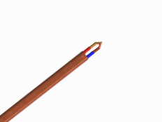
Standard ASTM E 230 color coding (United States) is used on all insulated thermocouple wire and extension wire when type of insulation permits. In color coding, the right is reserved to include a tracer to identify the ASTM E 230 type. Thermocouple grade wire normally has a brown overall jacket. For Types B, R and S the color codes relate to the compensating cable normally used.
Various national and international standard agencies have adopted color codes for the identification of thermocouple products. These generally differ from those specified in ASTM E 230. Additionally, the overall extension color code is used to identify connectors to specific thermocouple types.
Click here to download the thermocouple color codes table in PDF format.
What is response time?
A time constant has been defined as the time required by a sensor to reach 63.2% of a step change in temperature under a specified set of conditions. Five time constants are required for the sensor to stabilize at 100% of the step change value. Exposed junction thermocouples are the fastest responding. Also, the smaller the probe sheath diameter, the faster the response, but the maximum temperature may be lower. Be aware, however, that sometimes the probe sheath cannot withstand the full temperature range of the thermocouple type.
***The following technical information and application hints are intended to serve only as a guide for thermocouple selection.***

.png)
.png)